Guide for Mining Engineers and MCC Specialists responsible for VFD driven motors and long cable installations in harsh mining environments.
This guide explains how to coordinate earth leakage (EL) protection in Variable Frequency Drive (VFD) systems to reduce nuisance trips and improve uptime. The guidance is indicative and must always be verified against your site standards and commissioning procedures.
Quick Tips:
- Use selective measured settings and VFD Capable EL devices.
- Measure each feeder’s steady-state and start-transient leakage and set per-feeder EL thresholds and time delays to provide selectivity with upstream relays.
- Allow for VFD-induced leakage and the effect of long cable capacitance.
- Zone EL and verify upstream power quality (PQ) to prevent false trips.
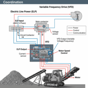
VFDs are widely used in mining MCCs for conveyors, crushers, and slurry pumps because they provide precise motor control and soft starts. However, they inherently produce high-frequency leakage currents through the motor cable and to earth. The switching frequency of the drive and the total cable capacitance (especially in long runs) contribute significantly to leakage.
- VFD filters: Installing output filters or reactors reduces leakage, but does not eliminate it.
- Cumulative effect: When several drives share a common EL device, the combined leakage can exceed trip thresholds.
Tip: When multiple VFDs are present, consider per-feeder EL detection and relays with VFD-cabable detection and programmable trip curves use a relay like the MA Relay (BBRTU). Discrimination still requires correct thresholds, CT Placement and commissioning tests.
Setting EL thresholds and time delays without sacrificing safety
Mining environments require sensitive earth leakage protection due to the high risk of shock and fire. Yet, if the EL trip level is set too low, harmless leakage from the VFD or long cables can trigger unwanted shutdowns.
Best practice guidelines (indicative):
- Trip threshold: Start from 100–300 mA for individual VFD feeders, depending on drive size and cable length.
- Time delay: choose a delay sufficient to ride through known transient leakage during starts; typical coordination delays are tens to a few hundred milliseconds, but final settings must be verified by injection/startup tests and be coordinated with upstream protection.
- Ramp coordination: Increase delay progressively for higher-rated circuits to achieve selectivity.
- Testing: Always verify with injection testing and simulated load starts before commissioning.
Use Type B earth leakage relays or VFD-compatible designs that can detect DC and high-frequency components. Devices like NewElec’s MA Relay are engineered for differential protection with programmable trip curves, allowing site engineers to fine-tune EL performance.
Coordinating EL with motor relays and MCC zoning
Proper zoning is crucial to prevent the entire MCC from tripping when only one motor feeder experiences a fault. Mining MCCs often contain 10–30 outgoing circuits feeding crushers, conveyors, or pumps. If all share a single upstream EL, minor leakage can cascade into a full shutdown.
Coordination guidelines:
- Assign individual EL relays per motor circuit or per zone.
- Use differential protection within each zone, with a higher threshold upstream.
- Integrate EL feedback into motor protection relays (like the MA Relay) for unified fault reporting.
- Ensure thermal protection and start supervision functions remain unaffected by EL delay settings.
By coordinating EL with the motor relay’s internal logic, engineers can achieve selective tripping: the affected feeder isolates, while upstream zones remain stable.
See start supervision and thermal coordination features in the MA Relay Deep Dive.
Managing long cable runs and EMI for Mining MCCs
Mining installations often involve long motor cable runs, sometimes exceeding 100–200 meters between the MCC and field equipment like conveyors or slurry pumps. These lengths amplify both capacitive leakage and electromagnetic interference (EMI).
Engineering considerations:
- Cable type: Use screened or armoured cables with symmetrical earth returns.
- EMC filters: Fit common-mode chokes or sine filters on the VFD output to minimize HF noise.
- Grounding: Ensure multiple low-resistance earth points to disperse high-frequency leakage safely.
- Segregation: Route signal and control cables separately to reduce induced noise in instrumentation.
EMI can mimic EL faults, particularly if shielding is terminated incorrectly or cable trays share noisy circuits. Mining sites that operate under variable loads, wet conditions, and conductive dust are especially vulnerable.
Verifying power quality upstream to prevent cascading trips
Even a perfectly tuned EL system can experience nuisance tripping if upstream power quality is unstable. Voltage dips, harmonics, or phase imbalance can cause spurious current flow to earth or drive internal protection to activate incorrectly.
PQ checks to include during commissioning:
- Voltage balance: ≤ 2% imbalance between phases.
- Harmonics: Maintain total harmonic distortion (THD) below 5%.
- Neutral earthing: Inspect for stray currents or shared neutrals between VFD panels.
- Feeder protection: Use relays capable of PQ monitoring, such as NewElec’s KD Feeder Relay range.
Stable PQ ensures accurate EL operation and extends the life of drives, relays, and motors. For advanced coordination, the PQ data can also feed into predictive maintenance dashboards, reducing unplanned stoppages.
Field commissioning checklist and common pitfalls
Use this indicative checklist to streamline commissioning and reduce startup troubleshooting:
- Verify cable lengths and insulation resistance for each circuit.
- Confirm VFD filters, reactors, or output chokes are installed as designed.
- Set EL thresholds 50% above the measured steady-state leakage current.
- Calibrate time delays progressively by MCC zone.
- Test the EL relay operation using current injection or portable testers.
- Validate the correct direction of CT installation (for differential EL relays).
- Check PQ stability during simultaneous conveyor or crusher startup.
- Record baseline leakage currents for future maintenance comparison.
Common pitfalls:
- Shared neutrals or earthing between panels.
- Oversensitive EL relays with default factory settings.
- Ignoring drive-specific leakage data from the manufacturer.
- Skipping re-tests after cable or motor replacement.
Following a structured commissioning plan avoids many of the nuisance trips that plague complex MCCs in mining plants.
For step by step examples, refer to the dedicated Q&A guide “How To Coordinate Earth Leakage Protection for VFDs in Mining MCCs” in the Knowledge Hub. The Q&A walks through two applied field scenarios, including a 90 kW conveyor VFD with a 150 m cable run and a 250 kW crusher on a soft starter with long feeds and multiple earth points.
In that guide you can see how measured leakage values, time graded settings, and thermal supervision are used to choose indicative trip thresholds and delays, and how these settings prevent nuisance trips while keeping personnel and equipment protected.
Strengthening Earth Leakage Performance Across Your Mining MCCs
Improving earth leakage performance in VFD based mining operations is not only about preventing nuisance trips. It is about stabilising the entire MCC ecosystem so conveyors, crushers, pumps, and ventilation systems operate predictably under high load and harsh conditions. When leakage behaviour is measured accurately and settings are coordinated across feeders, zones, and upstream devices, the result is a more resilient plant with fewer unplanned stoppages and reduced stress on motors, cables, and relays.
Engineers can further enhance system stability by pairing VFD compatible EL relays with motor protection devices that offer differential sensing, programmable curves, and thermal supervision. The MA Relay is designed specifically for these environments and provides the kind of fine tuning required when long cable runs, high switching frequencies, and EMC noise overlap. For a deeper technical breakdown of curve selection, filtering, and differential behaviour, refer to the MA Relay Deep Dive.
Before your next MCC upgrade or expansion, explore the relay options suited to your environment, load profile, and installation method. Use the Mining Comparison Guide to evaluate EL capability across models, and the Relay Selector to filter recommended solutions for your application. If you need help evaluating leakage behaviour or selecting the right protection architecture, a NewElec engineer can support your assessment and configuration planning.

Frequently Asked Questions (FAQs)
1. Why do multiple VFDs on a single MCC increase the risk of unwanted earth leakage trips?
When several VFD feeders share a common upstream earth leakage device, their combined high frequency leakage adds together. Even if each drive has acceptable leakage on its own, the cumulative value can exceed the upstream EL threshold, especially during starts or rapid load changes. This is why mining MCCs benefit from per feeder EL relays or zoned differential protection instead of relying on a single rooftop device.
Should VFD output filters always be used to reduce nuisance leakage?
Filters such as sine filters and common mode chokes help reduce high frequency noise, but they do not eliminate leakage completely. In long cable runs they may only reduce leakage by a percentage, not enough to allow extremely low trip thresholds. Filters should be used as part of a coordinated approach that includes correct EL relay selection, measured leakage values, time delays, and proper grounding practice.
How does incorrect cable shield termination lead to false earth leakage trips in mining environments?
If cable shields are bonded incorrectly, or terminated at only one end when both ends are required, the shield can act as an antenna for high frequency noise from nearby drives, conveyor starters, or crushers. This noise can create residual currents that appear to the EL relay as an imbalance. Proper screening, shield earthing, and segregation of power and control wiring significantly reduce this risk.
Why is insulation resistance testing not enough to set earth leakage thresholds for VFD feeders?
Insulation resistance tests measure low frequency or DC conditions, while VFDs operate using high frequency switching. A motor and cable may pass insulation tests yet still generate a high steady state leakage due to capacitance. Thresholds must be based on measured operational leakage while the drive is running, not only on IR values. Relying on IR alone often leads to EL settings that are too sensitive and prone to nuisance trips.
What commissioning data should be recorded to support long term earth leakage stability?
-
Recording baseline leakage levels during start up and steady load helps maintenance teams spot changes over time. Key data includes drive size and model, cable length and type, presence of filters, measured leakage at run and start, set thresholds, applied delays, and PQ conditions during testing. These records make troubleshooting easier and reduce repeated nuisance trips caused by small changes in grounding, cable routing, or equipment ageing.